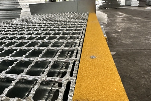
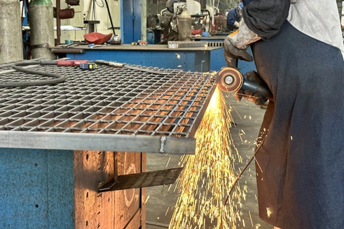
Steel grating size cannot be defined by panel length and width alone. A complete specification should identify the bearing bar size, bearing bar pitch, cross bar type and pitch, clear support span, panel dimensions, material, surface profile, finish and fastening method. These parameters work together to determine the grating’s weight, open area, load performance, drainage characteristics and suitability for fabrication.
This guide explains how to read and specify steel grating dimensions for industrial platforms, walkways, stair systems, trench covers and other structural applications. It is intended to help engineers, contractors and purchasing teams prepare a more complete request for quotation. Final load capacity and allowable span must always be verified against the applicable project standard, design loads and approved manufacturer data.
| Specification Item | What It Describes | Why It Matters |
| Bearing bar size | Depth and thickness of the main load-carrying bars | Strongly influences stiffness, weight and load capacity |
| Bearing bar pitch | Center-to-center distance between adjacent bearing bars | Affects open area, weight, load distribution and the passage of objects |
| Cross bar size and pitch | Size and center-to-center spacing of bars running across the bearing bars | Maintains spacing, stabilizes the panel and contributes to surface traction |
| Span | Clear distance between supports in the bearing bar direction | Required for load and deflection verification |
| Panel dimensions | Finished length and width of an individual grating panel | Controls layout, fabrication, installation and shipping |
| Surface profile | Plain or serrated bearing bars | Affects walking conditions and slip resistance |
| Material and finish | Carbon steel, stainless steel and the required surface treatment | Determines corrosion resistance and suitability for the service environment |
| Fastening method | Clips, bolts, welding or another approved connection method | Controls panel restraint, removal and maintenance access |
A typical steel bar grating panel contains load-carrying bearing bars running in one direction and cross bars running perpendicular to them. The bearing bars transfer loads to the supporting steelwork, while the cross bars maintain the spacing between bearing bars and help stabilize the panel.
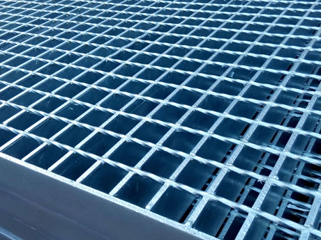
Bearing bars are the primary structural members in a steel grating panel. They must run between the structural supports. Their section is normally expressed as depth × thickness, such as 30 × 3 mm or 40 × 5 mm.
For example, a 30 × 5 mm bearing bar is nominally 30 mm deep and 5 mm thick. Increasing the bearing bar depth or thickness generally increases the amount of steel in the panel and may improve its load-carrying performance. However, bearing bar size should never be selected without considering the span, pitch, material grade, load type and allowable deflection.
Cross bars run perpendicular to the bearing bars. Depending on the manufacturing method, they may be twisted square bars, round bars, flat bars or other mechanically locked profiles. Their primary functions are to maintain bearing bar spacing, stabilize the grid and contribute to the walking surface.
Cross bars are not a substitute for correctly oriented bearing bars. A grating panel installed with the bearing bars running parallel to the supports may not provide the intended structural performance.
Banding bars are welded around the ends or edges of a finished panel. They can help protect exposed bearing bar ends, retain cut areas and provide a finished panel perimeter. Cutouts, penetrations and irregular panel shapes may also require banding according to the approved fabrication drawing.
Common bearing bar sizes vary by market, manufacturing standard and project requirement. Sino Grating’s regular manufacturing range includes the following examples:
| Bearing Bar Size | Nominal Depth | Nominal Thickness |
| 20 × 3 mm | 20 mm | 3 mm |
| 20 × 5 mm | 20 mm | 5 mm |
| 25 × 3 mm | 25 mm | 3 mm |
| 25 × 5 mm | 25 mm | 5 mm |
| 30 × 3 mm | 30 mm | 3 mm |
| 30 × 5 mm | 30 mm | 5 mm |
| 32 × 3 mm | 32 mm | 3 mm |
| 32 × 5 mm | 32 mm | 5 mm |
| 40 × 3 mm | 40 mm | 3 mm |
| 40 × 5 mm | 40 mm | 5 mm |
| 50 × 3 mm | 50 mm | 3 mm |
| 50 × 5 mm | 50 mm | 5 mm |
These dimensions are examples of regular manufacturing options, not automatic recommendations for a particular load. Custom bar sections may be considered when standard configurations do not meet the required span, load, weight or dimensional constraints.
Bearing bar depth is measured vertically. A deeper bearing bar can provide greater bending stiffness, but its suitability still depends on the complete grating configuration. A deeper bar installed at a wider pitch may perform differently from a shallower bar installed at a closer pitch.
Bearing bar thickness affects the cross-sectional area, panel weight and connection details. A thicker bearing bar may be required for demanding loads, fabrication conditions or specific standards, but it can also increase material consumption and cost.
For vehicle traffic, machinery loads or long support spans, buyers should consider purpose-designed heavy duty steel grating rather than selecting a standard pedestrian grating based only on panel thickness.

Pitch is the center-to-center distance between adjacent bars. It is not the same as the clear opening. Because the bars themselves have thickness, the unobstructed gap between two bars is smaller than the stated pitch.
Bearing bar pitch is measured from the center of one bearing bar to the center of the next. Regular options can include 30 mm, 34 mm and 40 mm spacing, subject to product type and manufacturing requirements.
A closer bearing bar pitch places more load-carrying bars within a given panel width. This generally:
Reduces the clear opening between bearing bars;
Increases the amount of steel and panel weight;
Influences load distribution across the panel;
Affects drainage, ventilation and light transmission;
Changes the ability of small objects to pass through the grating;
May increase material and galvanizing costs.
A wider pitch provides a more open panel and may reduce weight, but the proposed configuration must still satisfy the required load, deflection and safety criteria.
Cross bar pitch is measured in the direction of the bearing bar span. Common manufacturing options may include 38 mm, 50 mm and 100 mm, depending on the grating type and applicable specification.
Cross bar pitch influences panel stability, surface pattern and walking characteristics. A closer cross bar pitch creates more transverse contact points, while a wider pitch creates a more open surface. Cross bar spacing should be shown separately from bearing bar spacing in the purchase specification.
One of the most common procurement mistakes is treating pitch as the clear opening. For a simplified example, bearing bars installed at a 30 mm center-to-center pitch do not create a 30 mm clear gap. The actual opening depends on the thickness and profile of the bearing bars.
If the project has restrictions concerning small objects, footwear, maintenance tools or drainage debris, state the required clear opening or applicable safety criterion rather than relying on pitch alone. Applications requiring controlled openings may need a dedicated product such as ball-proof grating.
Span is the clear distance between supporting members measured in the bearing bar direction. It is one of the most important inputs in steel grating selection because the bearing bars act across this unsupported distance.
Panel length and structural span are not necessarily the same. A panel may extend beyond the clear opening to provide adequate bearing on the supporting steelwork. Therefore, an RFQ should state both the finished panel dimension and the clear support span.
Fabrication drawings should show the bearing bar direction with an arrow or another clear notation. In many layouts, the bearing bars run along the panel length and cross the shorter unsupported distance, but this must be confirmed from the actual support arrangement.
When preparing a layout, do not assume that the longest panel dimension is always the span direction. The correct direction is determined by the location of the supporting beams.
A single maximum span cannot be applied to every steel grating panel. Allowable span depends on:
Bearing bar depth and thickness;
Bearing bar pitch;
Material grade and mechanical properties;
Uniform, concentrated, line, impact or vehicle loads;
Required load combinations;
Allowable stress and deflection limits;
Support conditions and end bearing;
Applicable manufacturing and structural standards;
Corrosion allowance or expected section loss, where required.
The selected configuration should be checked against an applicable load table or a project-specific calculation. Published load data should only be used when its material, bar section, pitch, span definition, load type and deflection criteria match the proposed grating.
Finished grating panels are generally described by length × width, but the drawing must also identify the bearing bar direction.
Panel length: commonly follows the bearing bar direction and includes the required support bearing;
Panel width: is measured perpendicular to the bearing bars;
Clear span: is the unsupported distance between structural supports;
Structural opening: is the total opening to be covered and may require multiple panels.
The final panel dimensions should account for installation clearance, support width, adjacent panels, edge conditions, banding, removable sections and the selected fastening system.
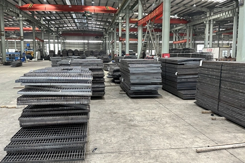
Steel grating raw panels are large, unprocessed panels intended for subsequent cutting and fabrication. Regular raw-panel formats may be produced at approximately 993 or 995 mm in width and up to 6000 mm in length, depending on the bar configuration. Current production availability should be confirmed before placing an order.
Finished panels are fabricated according to the approved layout and may include:
Cut-to-size external dimensions;
Banding bars;
Notches around columns or structural members;
Pipe and equipment cutouts;
Toe plates or kick plates;
Hinged or removable access sections;
Mounting holes and clip locations;
Plain or serrated bearing bars;
Hot-dip galvanized, painted or other specified finishes.
Raw panels may be suitable for distributors or fabricators with their own cutting and finishing capabilities. Project owners who require direct installation generally benefit from finished panels manufactured from approved grating layout drawings.
A grating description may combine the manufacturing method, bearing bar section, bearing bar pitch and cross bar pitch. For example, a supplier-specific notation such as:
W30 × 5 / 30 / 100
could be interpreted as:
| Code Element | Possible Meaning |
| W | Welded grating |
| 30 × 5 | Bearing bars nominally 30 mm deep and 5 mm thick |
| 30 | Bearing bars at 30 mm center-to-center pitch |
| 100 | Cross bars at 100 mm center-to-center pitch |
Model codes are not completely universal. The purchaser should obtain the manufacturer’s notation guide and confirm whether the code also identifies surface profile, banding, material or finish. Do not approve a product solely from an abbreviated code when a full written specification and drawing are available.
| Application | Important Selection Inputs | Product Direction to Review |
| Pedestrian walkway | Pedestrian load, support span, slip conditions, drainage, small-object requirements and removable access | Welded or press-locked grating with a verified walking surface |
| Industrial platform | Maintenance load, concentrated equipment loads, span, cutouts, toe plates, corrosion exposure and fixing | Steel bar grating fabricated to an approved platform layout |
| Vehicle or heavy equipment area | Wheel loads, axle loads, contact area, impact, traffic direction, fatigue and support arrangement | Heavy duty steel grating |
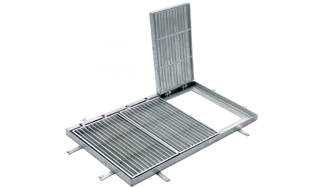
| Drainage trench | Clear opening, traffic category, support frame, drainage area, lifting requirement and surface profile | Steel trench cover grating |
| Industrial stairs | Tread width, tread length, nosing, bearing bar direction, fastening holes and slip conditions | Steel grating stair treads |
| Architectural or visual application | Grid alignment, opening size, surface appearance, finish, edge details and dimensional consistency | Press-locked steel grating |
The table provides a starting point only. Final product selection must be based on the project specification and approved engineering data.
Plain grating has a flat top surface. Serrated grating uses notches or teeth along the upper edge of the bearing bars to provide additional surface edges underfoot.
Serrated grating may be considered for outdoor walkways, industrial areas or locations exposed to water, mud or process contamination. However, the surface profile alone does not guarantee slip performance under every condition. The project should also consider footwear, drainage, contaminants, maintenance and the applicable safety requirement.
The required surface must be stated in the purchase order because plain and serrated panels with otherwise similar dimensions are not necessarily interchangeable.
After the dimensions and structural configuration have been selected, the purchaser should define the material and corrosion-protection system.
Carbon steel is widely used for industrial platforms, walkways, trenches and access structures. It can be supplied unfinished, painted or hot-dip galvanized according to the project environment and specification.
Hot-dip galvanizing is commonly specified for carbon steel grating used outdoors or in industrial environments. The galvanizing standard, required coating properties and permitted repair procedure should be stated in the order.
Cutting, welding, banding and major fabrication operations should be coordinated before the final surface treatment so that the finished panel receives the specified corrosion protection. Any field modification should follow the project’s approved coating-repair procedure.
Stainless steel grating may be considered when corrosion resistance, hygiene, appearance or chemical exposure makes galvanized carbon steel unsuitable. The stainless steel grade, surface treatment and fabrication requirements must be confirmed for the actual service environment.
A complete RFQ helps a manufacturer select an appropriate configuration and reduces the risk of quoting the wrong panel size or bar orientation. Include the following information whenever available:
Project name and installation location;
Applicable manufacturing, material and galvanizing standards, including the edition where required;
Grating manufacturing type, such as welded, press-locked or another specified construction;
Bearing bar depth and thickness;
Plain or serrated bearing bar surface;
Bearing bar pitch;
Cross bar type, size and pitch;
Material grade;
Surface finish or coating requirement;
Uniform, concentrated, line, vehicle, impact or other design loads;
Clear support span and support arrangement;
Allowable deflection or project performance criteria;
Finished panel length and width;
Bearing bar direction on every panel;
Panel quantity and total required area;
Cutouts, notches, banding and toe plates;
Required installation clearance;
Fastening method and required grating clips;
Drawings in PDF, DWG or another agreed format;
Inspection, documentation, marking, packing and delivery requirements.
If the final bearing bar size has not yet been selected, provide the loads, span, support arrangement and applicable design criteria instead of requesting a recommendation based only on panel dimensions.
A request for “1000 × 6000 mm steel grating” does not identify the bearing bar section, pitch, load, span, surface, material or finish. It is not sufficient for an accurate technical quotation.
The panel must normally extend beyond the clear opening to rest on its supports. Always state the structural opening, clear span, finished panel size and required support bearing separately.
The direction of the bearing bars determines how loads are transferred to the supporting structure. Every layout drawing should clearly mark this direction.
Pitch is measured from center to center. The actual clear opening is smaller and depends on the bar thickness or profile.
Vehicle applications can introduce concentrated wheel loads, dynamic effects and fatigue considerations that are not represented by a basic pedestrian uniform load. Submit vehicle data for project-specific review.
Large openings, closely spaced cutouts and irregular shapes can affect fabrication and panel behavior. Show all penetrations, banding and edge requirements on the drawing.
The fastening method should be coordinated with the grating pitch, bearing bar profile and supporting steelwork during the design stage. This helps avoid incompatible clips or unnecessary field drilling.
There is no single universal size. Common bearing bar sections include 20 × 3, 25 × 3, 30 × 3, 30 × 5, 40 × 5 and other configurations, but the correct size depends on the span, pitch, loads, material and performance criteria.
Finished panel dimensions are commonly written as length × width, but the bearing bar direction must also be shown. Do not rely on dimension order alone to determine the span direction.
Bearing bar pitch is the center-to-center spacing between the primary load-carrying bars. Cross bar pitch is the center-to-center spacing between the transverse bars that stabilize the panel.
A deeper bearing bar can increase stiffness, but allowable span also depends on bar thickness, pitch, material, load type, support conditions and deflection limits. The complete configuration must be verified.
Yes. Raw panels can be cut, notched and banded to produce finished panels. The fabricator should work from an approved layout showing panel dimensions, bearing bar direction, cutouts and edge details.
A 30 mm pitch places more bearing bars within the same panel width than a 40 mm pitch. This affects opening size, weight, cost and load distribution. Selection should be based on the required load performance, safety criteria and project specification.
At minimum, provide the application, loads, clear span, bearing bar direction, preferred bar size and pitch, panel dimensions, material, finish, surface profile, quantity and drawings. If some specifications are undecided, identify them clearly and request a technical review.
Sino Grating is a professional steel grating manufacturer with more than 20 years of industry experience. The company supplies a broad range of steel grating products, including welded steel bar grating, raw panels, press-locked grating, stainless steel grating, heavy duty grating, stair treads, trench covers and customized fabricated panels.
Share your design loads, clear support span, bearing bar direction, panel layout, material, surface finish and applicable project standard with the Sino Grating team. We can review the required specifications, fabrication details, grating layout and fastening options before preparing a project-specific quotation.
Contact Sino Grating to Request a Steel Grating Specification Review and Quote